

TSTN-065
Tunable Laser#
Introduction#
The Tunable Laser is part of the Rubin Calibration System, TSTN-066.
Monochromatic flatfield illumination is required to characterize the wavelength-dependent throughput of the Rubin optical system, including the filters, mirrors, lenses, and detector quantum efficiency, as a function of focal plane position. This use case requires a tunable source covering the full LSST wavelength range of 320–1125 nm in steps as small as 1 nm, with a linewidth not exceeding 1 nm FWHM.
The tunable laser subsystem fulfills this requirement using an Ekspla NT242 (Main) as the primary laser, with an Ekspla NT252 (Stubbs) serving as a backup with complementary spectral performance. Light from the selected laser is routed by a Fiber Coupling Unit (FCU) to two outputs: the flatfield projector (via a 20 m fiber) and the CBP (via a separate 20 m fiber). A direct port on the FCU with a power meter allows monitoring of relative laser output independently of the downstream instruments.
The laser enclosure is mounted on the rotating dome structure, in close proximity to the flatfield projector, to minimize fiber transmission losses. Because the Ekspla lasers were designed for stable laboratory operation, a dedicated environmentally-controlled enclosure was developed to maintain them within their specified 18–25 °C operating range under the variable thermal conditions of the open-air Rubin summit enclosure.
This note covers the laser hardware, the laser enclosure and its thermal control system, electronics and Ccontrol, and laser safety. The use of the tunable laser output within the flatfield projector optics is described in the Flatfield Projector (TSTN-060). The use within the CBP is described in the CBP (TSTN-067). Additionally, there is another tech note dedicated to the laser electrical cabinet (TSTN-068)
Laser Hardware#
The Ekspla Laser User Manual and other information can be found on Docushare.
Main Laser#
The primary monochromatic source is an Ekspla NT242 tunable diode-pumped solid-state laser system. It provides wavelength coverage from 300–2600 nm at a pulse repetition rate of 1 kHz, with pulse energies ranging from approximately 40–450 µJ depending on wavelength.
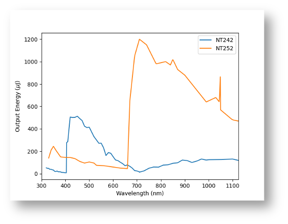
Fig. 1 Output energy of both lasers, NT242 and NT252, as a function of wavelength. Their coverage is highly complementary, particularly in the u-band.#
The NT242 consists of a 1064 nm master oscillator and pump laser coupled to an optical parametric oscillator (OPO), which generates output wavelengths from 405–2600 nm. Wavelengths between 300–405 nm are produced using sum-frequency generation between the fundamental 1064 nm output and the OPO signal beam. Depending on whether the output is generated via the OPO or sum-frequency generation, the wavelength step size ranges from 0.05–1 nm, meeting the 1 nm step requirement across the full LSST operational range. The system also incorporates a spectral cleaning unit employing prism-based filtering to suppress out-of-band light contamination.
The NT242 contains two BBO crystals that are hygroscopic and require continuous temperature regulation to prevent condensation damage. As a result, the laser must remain powered at all times, drawing approximately 15 W in standby mode. Full operation draws closer to 200 W.
Laser output is variable on multiple timescales. During thermalization after power-on, output increases slowly over several hours. Shorter-timescale jitter is also present and is typical of high-power pulsed lasers of this type. The shorter-timescale fluctuations are partially averaged out over the course of a flatfield exposure, while longer-timescale drifts are tracked and corrected for using the in-line photodiode in the projector monitoring system.
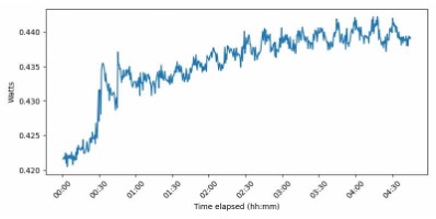
Fig. 2 Laser output power at 450 nm, measured at the FCU direct port during thermalization. Output fluctuates on multiple timescales; these fluctuations are tracked and corrected for using the in-line photodiode.#
Stubbs Laser#
A secondary Ekspla NT252 laser is referred to as the Stubbs laser as it was lent to Rubin Observatory by the Chris Stubbs lab at Harvard University. It serves as a backup monochromatic illumination source. Although broadly similar in architecture to the NT242, the NT252 provides different spectral performance that is highly complementary to the primary system, particularly in the u-band where the NT242 output is relatively low. The two lasers together provide effective coverage across the full LSST operational wavelength range.
Because the NT252 was not originally designed to interface directly with the FCU, an independent fiber-coupling controller was developed by Ekspla to provide equivalent fiber-routing capability. This required an additional LazServ machine that sits in the laser enclosure and is attached to both the Stubbs and Main laser.
There are a couple other ways in which the NT252 laser differs from the Main laser. It does not include a Spectral Cleaning Unit (SCU), and has outputs in the actual laser for the pump and first-oscillator wavelengths, 1098 and 532 nm, in addition to the selected wavelength beam.
Fiber Coupling Unit#
Laser output is routed to a Fiber Coupling Unit (FCU), which directs the beam from the selected laser to one of three outputs: two fiber-coupled ports and a direct port. The two fiber-coupled ports feed the flatfield projector and the CBP respectively, each via a 20 m silica step-index optical fiber (NA 0.12). A power meter at the direct port allows monitoring of relative laser output.
Laser Enclosure#
Mechanical Design#
All drawings for the laser enclosure can be found on Docushare Collection-14799.
The Ekspla lasers were designed for laboratory operation in an air-conditioned environment with a specified operating temperature range of 18–25 °C. Because the laser must be mounted on the rotating dome structure in close proximity to the flatfield projector in order to minimize fiber transmission losses, a dedicated environmentally-controlled enclosure was developed for summit operation.
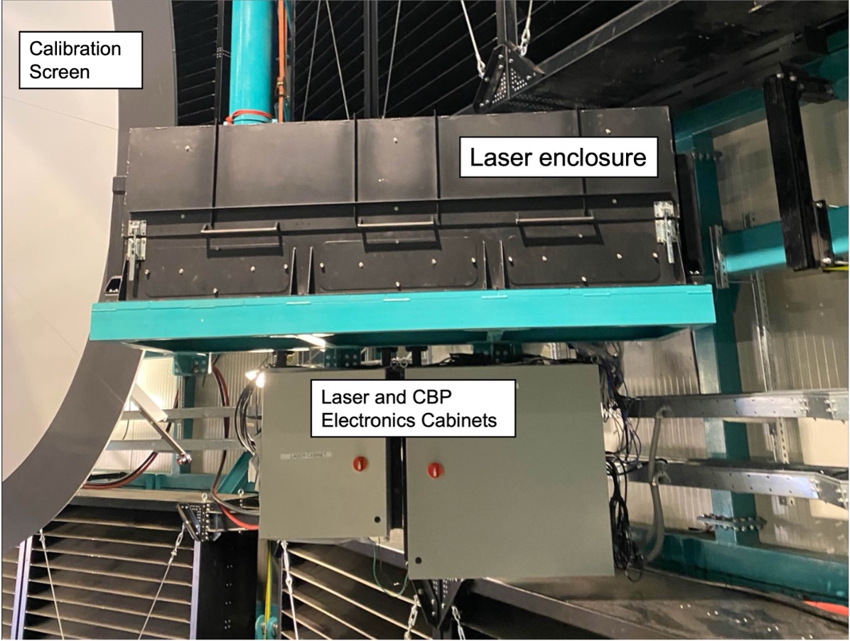
Fig. 3 The laser enclosure installed on the calibration screen support structure inside the Rubin Observatory dome. The electronics cabinets are secured below the platform.#
The Laser Enclosure houses:
Ekspla laser
laser power supply
thermal control hardware
environmental sensors
power monitoring instrumentation
It has a total mass of approximately 590 kg (1300 lbs) including the lifting bar, and sits on a platform connected to the calibration screen support structure. As viewed from the telescope, it is positioned to the lower right of the calibration screen.
Power and communications are routed to the enclosure from an electronics cabinet mounted directly below. The two 20 m optical fibers exit the enclosure and are carefully routed to the CBP and the flatfield projector respectively.
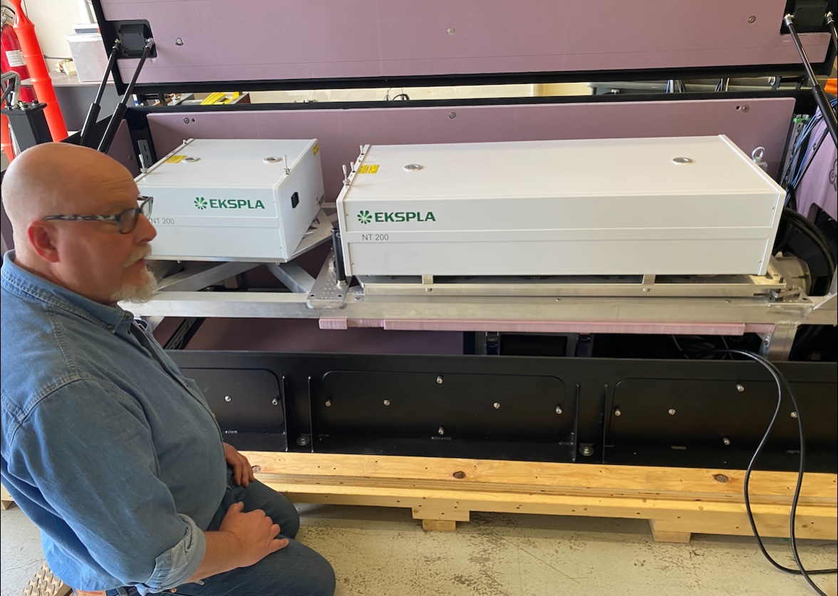
Fig. 4 The laser enclosure opened, with Ron Harris standing by. You can clearly see the frame that the laser and FCU are mounted on.#
The laser head and the FCU sit on a frame that is mounted directly over the power supply. When the laser needs to be removed from the enclosure, the frame can be lifted with a crane and caster wheels can be put on the frame and placed on the ground itself.
Warning
Fibers that run from the laser to the power supply can **never** be disconnected.
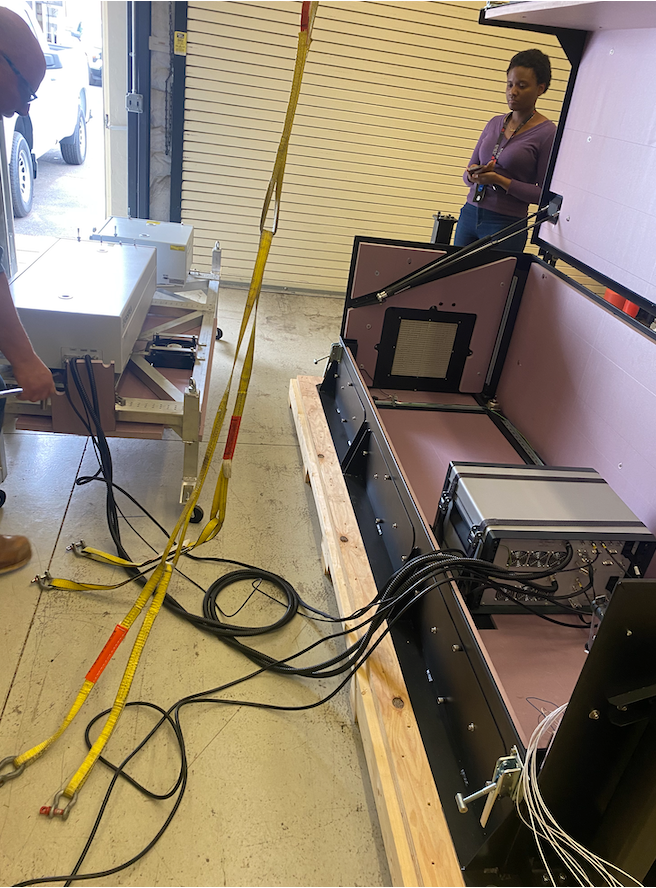
Fig. 5 The tunable laser is sitting on its frame to the left, with the power supply sitting in the base of the enclosure. You can also see Ron Harris (to the left) and Antanasia Jones (looking down).#
The laser and the FCU are both mounted on platforms. These connect to the frame at 3 points so they can be adjusted in tip and tilt to align with eachother. This alignment needs to be completed each time the laser is moved or replaced.
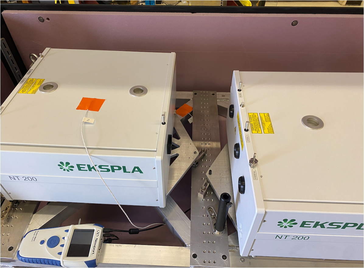
Fig. 6 The FCU sits to the left of the Tunable Laser. They can be aligned with eachother by adjusting the platforms each are mounted to independently.#
The cover is connected to 4 spring assemblies that help to open and close it. Because of the size and thinness of the top, it can easily be twisted. When opening, it is important to do so slowly using two handles furthest from eachother. The top aluminum cover has torn in some places due to torque.
The top is connected to an interlock, so if it’s opened, the laser will turn off. There are three ports that can be opened to access the bottom of the laser. These three panels have captive screws.
Thermal Control#
The laser head is mounted on an aluminum frame that sits over the power supply and is surrounded by an additional insulated enclosure. This additional insulated enclosure has dedicated forced-air circulation. Two resistive patch heaters are attached directly to the laser housing to provide supplemental heating during cold dome conditions. In practice, these external heaters are only required intermittently, because the laser’s own internal heaters maintain approximately 15 W of continuous heating. Under typical conditions, the internal heaters maintain the laser temperature near 18 °C when the system is in standby mode.
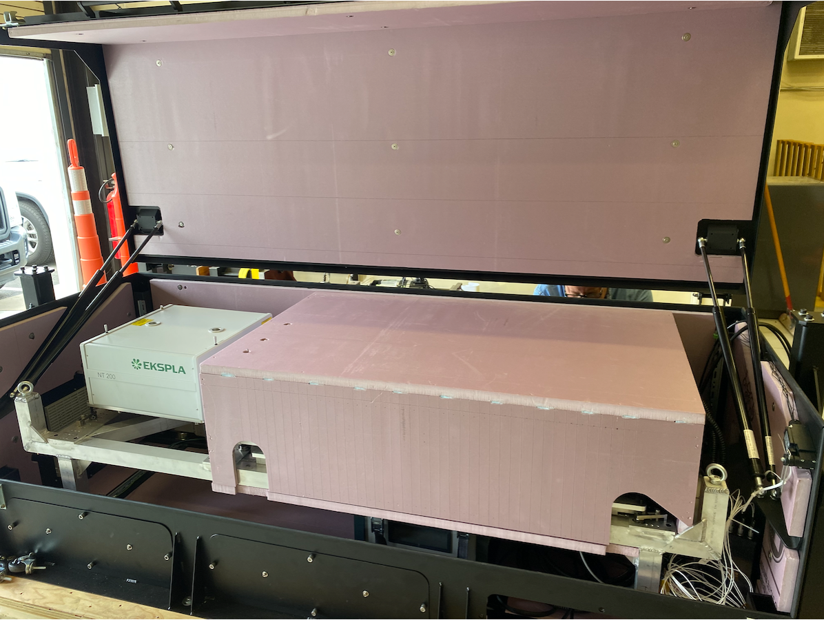
Fig. 7 The Laser has its own insulated enclosure made of pink insulation. This is in addition to the insulation secured to the inside of the whole enclosure.#
Thermal regulation of the laser enclosure is achieved through a combination of insulation, forced-air circulation, resistive patch heaters, and the continuously powered internal heaters that maintain the BBO crystals in a safe condition. There are two fans, one at the inlet (on the right if you are looking at the front), and one attached to the laser frame blowing air up into the laser specific enclosure. The outlet is at the other end, near the FCU. Both the inlet and outlet have air filters that need to be changed periodically.

Fig. 8 A fan is mounted directly to the laser frame, blowing air into the laser specific enclosure from the larger enclosure#
Although the laser is not strictly required to remain within its operational temperature range while idle, keeping it near the operating limits significantly reduces warm-up (or cool-down) time prior to calibration activities and reduces the number of thermal cycles, which are associated with increased risk of maintenance issues. During the transition from standby to operation, the laser temperature does briefly exceed the nominal 18–25 °C range; this excursion can affect overall output stability over that period. Fine-tuning of the thermal control system to reduce this excursion is ongoing.
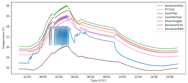
Fig. 9 Tunable laser and enclosure temperatures recorded during a representative night of monochromatic flat observations. The temperature rises rapidly after laser turn-on and oscillates as the ventilation fans cycle to maintain the system within its 18–25 °C operating range.#
Prior to shipment to Rubin Observatory, the enclosure design was validated through thermal testing in a controlled chamber in Tucson and at the summit of Kitt Peak National Observatory.
Electronics and Control#
There is a separate tech note that describes the Laser Electronics Cabinet TSTN-068.
Power and communications for the laser enclosure are routed from an electronics cabinet mounted on the calibration screen support structure directly below the enclosure platform. Power at 220 VAC/16A is delivered via slip rings to the rotating dome section. A UPS protects against short power interruptions and ensures the laser internal heaters remain powered at all times to protect the BBO crystals.
Both the NT242 and NT252 are controlled via RS-232 through a Moxa serial device server. A more limited Ethernet interface is also available on each laser. The FCU is controlled separately; because the NT252 was not originally designed to interface with the FCU, an independent fiber-coupling controller was developed by Ekspla for that laser.
The tunable laser is commanded throught the TunableLaser CSC. Additionally, there is a windows machine in the laser electronics cabinet that can be accessed at laser-powermonitor.cp.lsst.org. This machine is used to read the power meter in the laser enclosure as well as has downloaded several useful GUIs to communicate directly with the laser, including CANBrowser, as developed by Ekspla.
Laser Safety#
The NT242 and NT252 are Class-4 laser systems, requiring multiple engineering and operational safety controls. Although the downstream projector and CBP optics significantly expand the beam and reduce irradiance at exit apertures, direct exposure to the unattenuated laser beam within the enclosure remains hazardous.
There are 4 main interlocks for this laser:
Laser Enclosure Lid
When the lid to the enclosure (black coffin) is opened, power is cut to everything within the enclosure
Laser Key:
The laser cannot be operated until the key is inserted and turned to ON
The key will only be available to a restricted group
Laser GIS
This interlock is always enabled
If the interlock is triggered, the laser stops propagating immediately
Audio trigger
If the optical fiber is misaligned with the laser beam it produces a 1kHz signal.
If this sound is heard by and internal microphone, the interlock is triggered
If the interlock is triggered, the laser stops propagating immediately
The laser GIS is integrated with the observatory’s Global Interlock System (GIS). Laser operation is automatically inhibited under conditions including:
Dome access events
Emergency-stop activation
Earthquake triggers
Telescope safety interlock events
Additionally, there are several administration controls in place. This is especially necessary as the L7 gate has been bypassed in the GIS system
A member of the calibration or observing team, approved by Safety, will get the key from a secured location.
Before travelling to L8, an announcement will be made on Slack and over the radio that laser operations in the dome will commence.
When they travel to L8, they will close the door on L5, which leads to the elevator and stairwell.
After turning the key and returning to L2, another announcement will be made that no one is to move to L7 or L8
Installation#
The laser enclosure sits on a platform connected to the calibration screen support structure and is positioned to the lower right of the calibration screen as viewed from the telescope. It was installed as part of the broader calibration screen and projector installation effort. The two 20 m output fibers are carefully routed from the enclosure to the flatfield projector (at the center of the calibration screen) and to the CBP platform respectively.
The enclosure power and communications cables are routed from the electronics cabinet mounted directly below the platform. The GIS interlock connections to the enclosure lid sensors and keyed interlock switch are made as part of commissioning and verified before any laser operation is permitted.
It is necessary to remove the laser enclosure about 2 times per year. Since the overhead crane cannot access this point, a separate point on the top of the dome has been set to use as a hoist point. There is a specialized lifting fixture (yellow bar) that must be installed on the laser first.
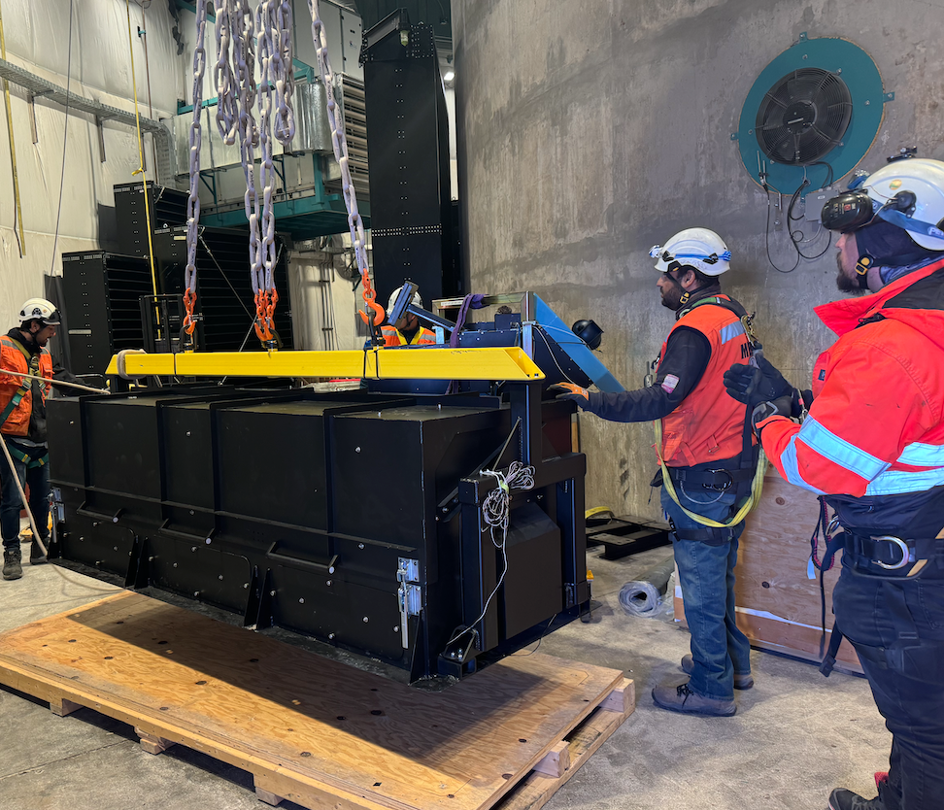
Fig. 10 Lifting fixture mounted on the laser enclosure, being brought from L5 up to L7 with the overhead crane. In teh picture are also Alexis Aracena and Hernan Herrera, who were instrumental in installation of all the calibration hardware.#
Maintenance and Past Damage#
We have planned for maintenance on the laser once a year. This requires bringing the laser down and cleaning optics and adjusting mirrors, etc. While one laser is under maintenance, the other could be installed. Thus far, we have had Ekspla representatives come out for this maintenance.
We have to date had two major issues with the NT242 laser:
After maintenance in Tucson, we had some dust get onto the tip of a fiber. That caused a catestrophic failure, and the laser had to be sent back to Ekspla for repair
During a recent maintenance trip in Chile, after a thermal board was replaced, damage occured to a polarizer optic. It is expected this happened due to ongoing damage due to the broken thermal board, which was then exacerbated when the new board was installed.
Weekly laser tests should identify if the output of the laser is changing over time and may trigger an earlier scheduling of maintenance.
Additionally, the two air filters on the laser enclosure should be replaced twice a year.
Operations#
The laser must remain powered at all times to protect the BBO crystals. In standby, the system draws approximately 15 W; this is normal and expected.
Before activating the laser, all safety interlocks must be confirmed in the nominal state and the dome must be verified clear of personnel, in accordance with the laser safety procedures. This means that first a key must be brought up to Level 8 and the laser is then “turned on” and can be communicated with. The TunableLaser CSC can then be enabled. Once the tunable laser is enabled, and the interlocks are all enabled, the laser can be commanded to start “lasing”.
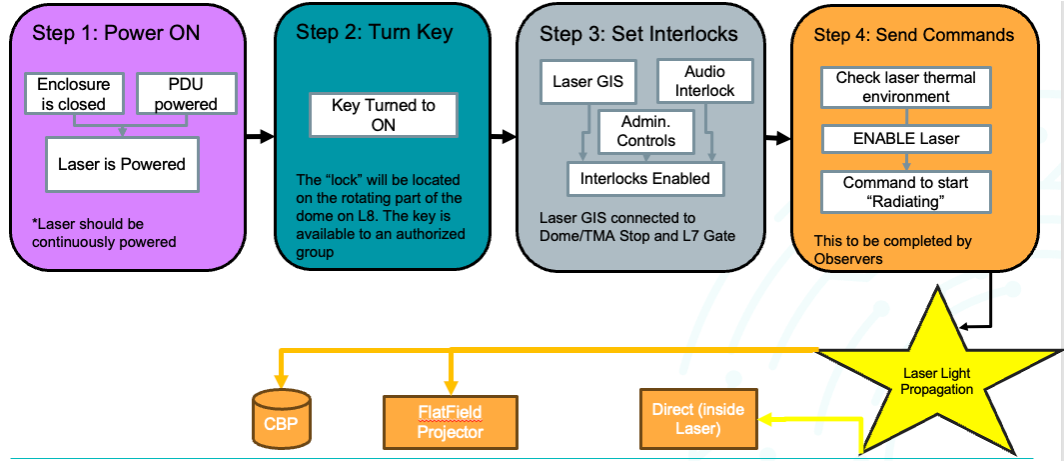
Fig. 11 Sequence of activities for actually turning the laser “ON”#
In cases where the NT242 is unavailable, the NT252 can be used as a backup. It requires its own independent fiber-coupling controller and provides complementary spectral performance, particularly at u-band wavelengths where the NT252 has substantially higher output energy than the NT242.
Troubleshooting#
All troubleshooting documentation can be found on the Observatory Operations Documentation Confluence Pages for MTCalSys.